


Microchip Technology SMART E70, V70, & 71 32-Bit Microcontrollers
Microchip Technology SMART E70, V70, and V71 32-Bit Microcontrollers are members of a family of Flash MCUs based on the high-performance 32-Bit Arm® Cortex®-M7 Processor with a Double Precision Floating Point Unit (FPU). These devices operate at up to 300MHz and feature up to 2048Kbytes of Flash and up to 384Kbytes of multiport SRAM. The on-chip SRAM can be configured as Tightly Coupled Memory (TCM) or system memory. A multiport access to the SRAM guarantees a minimum access latency.
Features
- Core
- Arm Cortex-M7 running at up to 300MHz
- 16 Kbytes of ICache and 16 Kbytes of DCache with Error Code Correction (ECC)
- Single- and double-precision HW Floating Point Unit (FPU)
- Memory Protection Unit (MPU) with 16 zones
- DSP Instructions, Thumb®-2 Instruction Set
- Embedded Trace Module (ETM) with instruction trace stream, including Trace Port Interface Unit (TPIU)
- Memories
- Up to 2048 Kbytes embedded Flash with unique identifier and user signature for user-defined data
- Up to 384 Kbytes embedded Multi-port SRAM
- Tightly Coupled Memory (TCM) interface with four configurations (disabled, 2x32Kbytes, 2x64Kbytes, 2x128Kbytes)
- 16Kbytes ROM with embedded Boot Loader routines (UART0, USB) and IAP routines
- 16-bit Static Memory Controller (SMC) with support for SRAM, PSRAM, LCD module, NOR, and NAND Flash with on-the-fly scrambling
- 16-bit SDRAM Controller (SDRAMC) interfacing up to 256MB and with on-the-fly scrambling
- System
- Embedded voltage regulator for single-supply operation
- Power-on-Reset (POR), Brown-out Detector (BOD), and Dual Watchdog for safe operation
- Quartz or ceramic resonator oscillators: 3 to 20MHz main oscillator with failure detection, 12MHz or 16MHz needed for USB operations. Optional low-power 32.768kHz for RTC or device clock
- RTC with Gregorian calendar mode, waveform generation in low-power modes
- RTC counter calibration circuitry compensates for 32.768kHz crystal frequency variations
- 32-bit low-power Real-time Timer (RTT)
- High-precision 4/8/12MHz factory-trimmed internal RC oscillator with 4MHz default frequency for device startup. In-application trimming access for frequency adjustment.
- 32.768kHz crystal oscillator or embedded 32kHz (typical) RC oscillator as source of low-power mode device clock (SLCK)
- One 500MHz PLL for system clock, one 480MHz PLL for USB high-speed operations
- Temperature Sensor
- One dual-port 24-channel central DMA Controller (XDMAC)
- Low-Power Features
- Low-power Sleep, Wait and Backup modes, with typical power consumption down to 1.1μA in Backup mode
- Ultralow-power RTC and RTT
- 1 Kbyte of backup RAM (BRAM) with dedicated regulator
- I/O
- Up to 115 I/O lines with external interrupt capability (edge- or level-sensitivity), debouncing, glitch filtering, and On-die Series Resistor Termination
- Five Parallel Input/Output Controllers (PIO)
- Voltage
- Single supply voltage from 1.7V to 3.6V
- Peripherals
- One Ethernet MAC (GMAC) 10/100 Mbps in MII mode and RMII with dedicated DMA. IEEE1588 PTP frames and 802.3az Energy-efficiency support. Ethernet AVB support with IEEE802.1AS Time-stamping and IEEE802.1Qav credit-based traffic-shaping hardware support.
- USB 2.0 Device/Mini Host High-speed (USBHS) at 480 Mbps, 4-Kbyte FIFO, up to 10 bidirectional endpoints, dedicated DMA
- 12-bit ITU-R BT. 601/656 Image Sensor Interface (ISI)
- Two master Controller Area Networks (MCAN) with Flexible Data Rate (CAN-FD) with SRAM-based mailboxes, time- and event-triggered transmission
- Three USARTs. USART0/1/2 support LIN mode, ISO7816, IrDA®, RS-485, SPI, Manchester and Modem modes; USART1 supports LON mode.
- Five 2-wire UARTs with SleepWalking support
- Three Two-Wire Interfaces (TWIHS) (I2C-compatible) with SleepWalking support
- Quad I/O Serial Peripheral Interface (QSPI) interfacing up to 256MB Flash and with eXecute-In-Place and on-the-fly scrambling
- Two Serial Peripheral Interfaces (SPI)
- One Serial Synchronous Controller (SSC) with I2S and TDM support
- One High-speed Multimedia Card Interface (HSMCI) (SDIO/SD Card/e.MMC)
- Four Three-Channel 16-bit Timer/Counters (TC) with Capture, Waveform, Compare and PWM modes, constant on time. Quadrature decoder logic and 2-bit Gray Up/Down Counter for stepper motor
- Two 4-channel 16-bit PWMs with complementary outputs, Dead Time Generator, and eight fault inputs per PWM for motor control, two external triggers to manage power factor correction (PFC), DC-DC, and lighting control
- Two Analog Front-End Controllers (AFEC), each supporting up to 12 channels with differential input mode and programmable gain stage, allowing dual sample-and-hold at up to 2Msps. Gain and offset error autotest feature
- One 2-channel 12-bit 1Msps Digital-to-Analog Controller (DAC) with differential and oversampling modes
- One Analog Comparator (ACC) with flexible input selection, selectable input hysteresis
- Cryptography
- True Random Number Generator (TRNG)
AES: 256-, 192-, 128-bit Key Algorithm, Compliant with FIPS PUB-197 Specifications - Integrity Check Monitor (ICM). Supports Secure Hash Algorithm SHA1, SHA224, and SHA256
- True Random Number Generator (TRNG)
- Packages
- LQFP144, 144-lead LQFP, 20x20mm, pitch 0.5mm
- LFBGA144, 144-ball LFBGA, 10x10mm, pitch 0.8mm
- LQFP100, 100-lead LQFP, 14x14mm, pitch 0.5mm
- TFBGA100, 100-ball TFBGA, 9x9mm, pitch 0.8mm
- LQFP64, 64-lead LQFP, 10x10mm, pitch 0.5mm
Development Tools
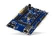
Microchip Technology SMART™ SAMV71 Xplained Ultra Evaluation Kit
Designed for prototyping SAM V71, SAM V70, SAMS70, and SAM E70 ARM® Cortex®-M7.
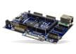
Microchip Technology DM320113 SAM E70 Xplained Ultra Evaluation Kit
Hardware platform for evaluating the ATSAME70 and ATSAMS70 MCU families.
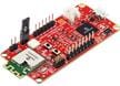
Microchip Technology APGDT006 CAN Bus Analyzer FD Tool
An easy-to-use, cost-effective CAN Bus monitor for developing and debugging high-speed CAN networks.

Microchip Technology WBZ351 Curiosity Board (EV19J06A)
Demonstrates the features, capabilities, and interfaces of the WBZ351PE RF Module.
Microchip Technology WBZ450 Curiosity Board (EV22L65A)
Demonstrates the features, capabilities, & interfaces of Microchip’s WBZ450PE BLE/Zigbee® RF Module.
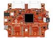
Microchip Technology EV87E90A SAM E70 Motor Control DIM
Features a SAME70 144-pin TQFP Arm® Cortex® M7 microcontroller.
Microchip Technology WBZ451HPE Curiosity Board
Designed to prototype the BLUETOOTH® Low Energy and Zigbee® RF Module.
Related Products

Microchip Technology 32-Bit SAM Microcontrollers
MCUs powered by Arm® Cortex® CPUs offering performance, power efficiency, and design flexibility.
Microchip Technology 32-Bit SAM V Microcontrollers
Arm® Cortex®-M7 based automotive MCUs optimized for in-vehicle infotainment connectivity.
Microchip Technology SMART S70 Arm-Based Flash MCUs
Microcontrollers based on the high-performance 32-bit ARM Cortex-M7 processor with FPU.

Microchip Technology 32-Bit SAM E Microcontrollers
Mid-performance Arm® Cortex®-M4F based MCUs and high-performance Arm Cortex-M7 based MCUs.
Related Solutions

Microchip Technology Functional Safety Solutions
Offer robustness, reliability, and safety to end-products.
Block Diagram
